CENTRAL INSTITUTE OF PLASTICS ENGINEERING & TECHNOLOGY
Question Bank
Electrical & Electronics Engineering Lab 2
Course: DPMT
Semester: I Sem
Subject: Electrical & Electronics Engineering
Experiment No. – 1
Aim of the experiment: Study of measuring instruments – Ammeter – Volt meter –Watt meter etc.
Students, watch these videos and materials for the basic information of some of the measuring instruments and try to understand.
https://www.youtube.com/watch?v=DXNoKuBzmk
In your electrical engineering copy write the experiment in this arrangement
Experiment No. – 1
Aim of the experiment: Study of measuring instruments – Ammeter – Volt meter –Watt meter etc.
Voltmeter-The instrument which measures the voltage or potential difference in volts is known as the voltmeter.
The voltmeter constructs in such a manner that their internal resistance always remains high. If it connects in series with the circuit, it minimises the current which flows because of the measurand voltage. That disturbs the reading of the voltmeter. The voltmeter always connects in parallel with the circuit so that the same voltage drop occurs across it. The high resistance of the voltmeter combines with the impedance of the element across which it is connected. And the overall impedance of the system is equal to the impedance that the element had. Thus, no obstruction occurs in the circuit because of the voltmeter, and the meter gives the correct reading.
Ammeter:
The Ammeter is a measuring instrument used to find the strength of current flowing around an electrical circuit in unit Amperes.
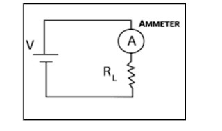
Schematic and Working of a circuit using Ammeter
In order for an ammeter to measure a device’s current, it must be connected in series to that device. This is necessary because objects in series experience the same current.
Wattmeter:Wattmeter is an instrument used to measure the electrical power.
Schematic and Working of a circuit using Wattmeter
The analog wattmeter is an electrodynamic instrument. The device consists of a pair of fixed coils, known as current coils, and a movable coil known as the potential coil. The current coils are connected in series with the circuit, while the potential coil is connected in parallel.
The current through the fixed coil of the wattmeter will be equal to load current and the voltage across the pressure coil of the wattmeter will be equal to load voltage and the wattmeter measures the average real power absorbed by the load.
Instruments available at market for Laboratory


.webp)

Thanks for the messages.